Steve White's Trix Twin Model Railway Website (established in 1999)

AC Loco Maintenance

AC loco mechanism

AC Motor Parts List

AC loco underside

How The Loco Works

The electric motor requires a 12-14 volts supply.

The loco picks up current from the outside track (right or left 
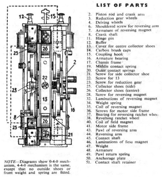
rail) by the side collector shoes (25). Note that these side shoes may be fitted either to the near side or to the off side of the loco.

In the 4-4-0 loco, current is picked up from one of the outer rails by collector shoes fitted to the tender. Electrical connection from tender to
4-4-0 loco is made through the tender towing pin, although a few 4-4-0's have a wire connection between loco and tender.

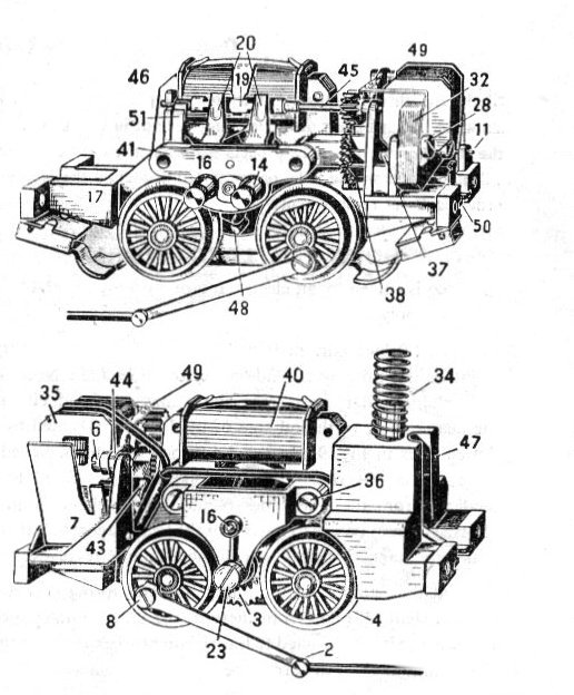
From the side shoes (which are insulated from the chassis) current passes to the coil of the field magnet (40) making a magnetic field in which the armature (48) revolves.

Current then passes via the middle contact spring (19) to the contact shaft (45) and from there to the outer contact springs (20). The current flows through the carbon brushes to the commutator of the armature.

The rotary motion of the armature turns the pinion gear wheel on the armature shaft (just seen behind the nearest pole winding (48) which drives the reduction gear wheels.

The smaller of these engages with teeth on the driving wheels (4) and makes them rotate, driving the Ioco along the track.

REVERSING
Four successive quarter revolutions of the contact shaft (45) give us
1. Forward speed.
2. Stop.
3. Reverse speed.
4. Stop.

Because of the inter-action between the springs (19 and 20) and the contacts of the contact shaft (45), the direction of the current through the armature (48) is changed so that in positions I and 3 the motor runs in the clockwise or anti-clockwise direction respectively. In positions 2 and 4, however, the springs (20) touch insulated portions of the shaft, the current is interrupted and the motor stops.

CLEANING
After long use the loco may need an overhaul.
To dismantle the loco proceed as follows, having first spread out a sheet of paper to save small screws, etc., from falling on to the floor.

Dismantling Locos

To dismantle the 4-4-0 Loco

  1. Undo the brass screw holding the front bogie assembly to the frame and remove this assembly.
  2. Undo the two small bolts fixing the crank arms to the rear driving wheels.
  3. Undo the two screws at the rear of the cab and remove the weight.
  4. The motor and direction mechanism can now be lifted as a single unit out of the frame.

To dismantle the 0-4-0 Loco

  1. As for 2 above
  2. Unscrew the buffers (12) from the buffer beams. In tender locos, countersunk screws take the place of buffers in the rear beam.
  3. Take off engine body, weight (47) and its spring (34).
  4. The motor and direction mechanism is now ready for dismantling.

Continue for either type of Loco.

  1. Undo the motor side frame screws (36).
  2. Remove the side frame (41). Do not prise off one end only, but ease it off with a gentle rocking motion. The brushes, if free, should spring out of their holders as the frame comes away. Take care not to bend the outer contact springs (20).
  3. Turn the armature (48) until one of the poles is centered between the driving wheels.
  4. Lift out the armature and commutator complete.
  5. Remove the contact shaft (45), taking care not to lose the contact shaft retainer (51) and spring contact.


(a) Clean out the grooves between the commutator segments using a sharpened match stick.
(b) Wipe over the commutator surface with a piece of clean cloth wrapped around a small wood splint. If very dirty moisten the cloth with a spot of contact cleaner or lighter fuel.
(c) With a sharpened match stick remove any fluff or dirt from the gear pinion. Wipe off any fluff, etc., from the armature poles.
(d) Clean the carbon brushes: (l) by rolling them beneath a finger on a piece of paper to ensure the sides are clean, (2) by rubbing the brush face VERY LIGHTLY on a piece of fine emery cloth from which most of the abrasive has been worn off. Be careful to hold the brush square so as not to wear it down on one side and do not stretch or distort the spring in the process.
(e) Now clean the side frame, unscrewing and removing the brush caps. See that the holders are free from dirt by passing a pipe cleaner through them.
(f) Wipe the outer contact springs and the segments on the contact shaft (45) with a cloth.
(g) Clean valve gear and inside of loco frame with a soft brush.
(h) Before reassembling put a drop of oil on the gear of the armature shaft.
(i) To clean the collector shoes, wipe over with a clean piece of cloth.

Reassembly

  1. Replace the armature
  2. Replace contact shaft, spring contact, and retainer.
  3. Very carefully refit the motor side-frame seeing that the two shoulders fit evenly into the frame and that the end of the armature shaft fits into its bearing. Replace the screws from the off side and screw them up. GIVING EACH ONE HALF A TURN AT A TIME. It is essential that each screw is evenly tightened, otherwise the side frame may be drawn on crookedly and the armature shaft may jam.
  4. NB: the contact shaft's metal contacts should line up with the outer contact springs. You may need to refit the contact shaft so it engages the next tooth of the ratchet wheel cog. Failure to line up the contact shaft correctly will result in no movement of the loco.    
  5. Replace brushes in their holders with the carbon ends towards the commutator and screw up the caps ONLY FINGER TIGHT.
  6. The motor and direction mechanism is refitted in reverse order to dismantling.
  7. When refitting the tender to 4-4-0 locos it is important that the coupling link and pin are free from oil and that the spring wires grip the pin firmly, ensuring a good electrical contact.

--Return to Operating & Servicing Page

www.TRIX.co.uk