HOW YOUR TRIX TWIN RAILWAY WORKS
T is theTransformer. It reduces the high
voltage (240v) of the A.C. house mains to a value that is both safe and convenient for
operating the train (14v).
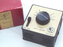
R is the controller. Current must pass
through this controller to the track to run the locos. The black knob K
regulates the amount of current supplied by the transformer, and makes a loco on the track
go faster or slower. The key U to the left of this black knob K, causes
the loco to stop and to reverse its direction of travel.
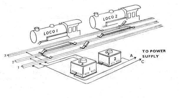
It will be seen that current is supplied to rails 2 and 3,
therefore the loco is placed on the track facing in that direction which will bring its
side shoes into contact with rail 3.
Switching on the current and turning the resistance knob
about half way round to the right will start the loco.
To stop the loco it is necessary to interrupt the current
(key U). This will cause the locomotive to stop. With a second interruption the locomotive
will move again, but this time in the opposite direction. A third will stop it, while a
fourth will cause it to run again in its original direction, the speed of running in each
direction being controlled by the resistance knob.
If the loco is lifted from the track and faced in the
opposite direction, the above operation has no effect since there is no current at present
being supplied to rail No.1.
If, however, the plug is taken out of the right-hand (blue)
socket on the terminal rail and put into the left-hand (white) socket, the loco will work
again.
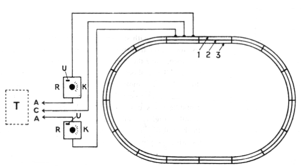
The three sockets on the terminal rail in
Fig. 1 are connected as follows
The left-hand (or white disc) to rail No. 1.
The middle (or red disc) to rail No. 2.
The right-hand (or blue disc) to rail No. 3.
Make sure that the wire marked C goes
direct from the power supply to the middle socket on the terminal rail which is identified
by a RED disc.
AUTOMATIC CUT-OUT
Steam locos are provided with a safety valve which is set
to blow off if the boiler pressure exceeds a certain value. This saves the boiler from
bursting.
Trix locos, of course, are not steam driven, but all the same their motors must be
protected. Therefore, within your controller is a device which automatically protects not
only the loco and the transformer, but also the controller itself from the effects of
overload and "short circuit." This cut-out is, in fact, an electrically operated
safety valve, and if for any cause the current flowing in the circuit is excessive, the
safety valve operates and immediately the key U will jump from its normal vertical
position into a sloping position towards the words " Cut Out "; current in that
circuit is then completely cut off. No current will flow again until the key U has been
restored to its vertical position. If, therefore, your key U "trips" and springs
forward with a click, it indicates that there has been an overload on that circuit. In
this case centre the key again. If it stays in its normal position the cause for tripping
has righted itself.
If, on centering, the key " trips" as soon as the
finger is removed, it means either that there is a short circuit on the track somewhere
(e.g. some metal object resting across the live rails) or that the loco is taking
excessive current through being overloaded with too many vehicles, or because it needs
oiling or cleaning.
To determine if the cause for tripping is in the loco or
the track, remove the loco and centre the key U. If it stays at centre but immediately
trips again when the Ioco is replaced, the fault is in the loco. If, however, the key U
when centered "trips" even when the loco is off the track, then the short
circuit is on the track and must be found and remedied.
Each time a suspected short circuit is put right, centre
the key and when finally the trouble has been corrected it will stay vertical in its
normal position. The key U is also needed for changing direction of the train.
ON NO ACCOUNT HOLD THE KEY U IN THE CENTRE POSITION, as
this is equivalent to screwing down a safety valve and is against all rules of
engineering.
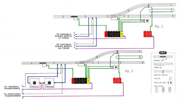
BOOST RAILS
On full-size and model electric railways the conductor
rails are subject to voltage drop. This means that the parts of the track which are remote
from the source of current supply or main feed will not be receiving the same amount of
current because the steel rails set up a resistance.
To overcome this use extra terminal rails, the centre
contacts of which are wired to the "C" of the power supply. Boost rails should
be inserted into the track at a distance from the main feed ; the number of rails to be
used will depend upon the size of your layout.
|